Math
155B – Topics in Computer Graphics – Spring 2020
Project #3 – Geometry shader creating a surface with raised triangular bumps.
Overview: For this assignment, you will write a geometry shaders to convert triangles to triangles with raised triangular centers. See the end of this document for sample images.
Due date: Thursday, May 7, 9:00pm. Upload all source files and GLSL files to the shared google drive (create a new folder named “Project3”. Also upload a PDF file with one or more images and the Acknowledgement of Assistance statement.
You should base your code on the Project 1 code. The primary change is to the shader files (the GLSL code). The changes to the main program are primarily to rename files, and to compile also a geometry shader.
The main aspects of your program will be:
· The existing main program renders a (re-meshable) flat ground plane as triangle strips.
· You will add a geometry shader to the shader program to replace each triangle by a triangle with a raised triangular middle section. This will require changes to the vertex shader also, but mostly renaming of variables, and removing the wave action.
· Different parts of the geometry rendered by the geometry shader will be given different material properties (esp., different diffuse properties).
· Your fragment shader will render with Phong lighting --- the existing fragment shader in EduPhong.glsl can be used unchanged.
· Your program should render similar to the pictures below.
Suggested steps for completing the project.
1. Start with the code from your Project #1. You will probably want to write a vertex shader and geometry shader more-or-less from scratch, but your old vertex shader will have a lot of code you want to keep. For some very simple geometry shader code, see the program SimpleGeometryShader at the textbook’s web site. You can also get the GLSL file NormalViewer.glsl from the GlGeomShapesTester program that renders normals, NormalViewer.glsl. These programs have geometry shaders that will help you see the syntax for geometry shaders.
2. Be sure to work with a *copy* of your Project 1 files, so Project 1 is still in your files (for grading and maybe future use).
3. Changes to the C++ code are primarily.
a. It is suggested to change your main .cpp and .h filenames, say to TriangularBumps[.cpp,.h], (old names with GlslWaves[.cpp,.h]. You will also need to change the #include’s.
b. In the main program, where the shaders are compiled and linked.
i. First, update the file name for your GLSL file.
ii. Second, add a line to compile to your geometry shader.
iii. Third, in the line linking the shader program, add the geometry shader as a third shader to include in the program.
4. In your old vertex shader, remove the code that changes the y value. Thus the vertices from the vertex shader all have y value equal to 0, and there are no waves. It will still be useful to pass the original vertex position (untransformed by the model view matrix to the geometry shader.
5. Discard your old fragment shader from Project 1, and just use the PhongPhong fragment shader from EduPhong.glsl.
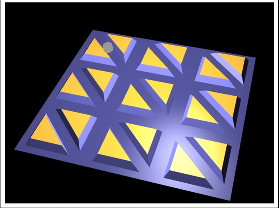
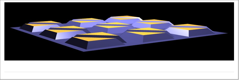
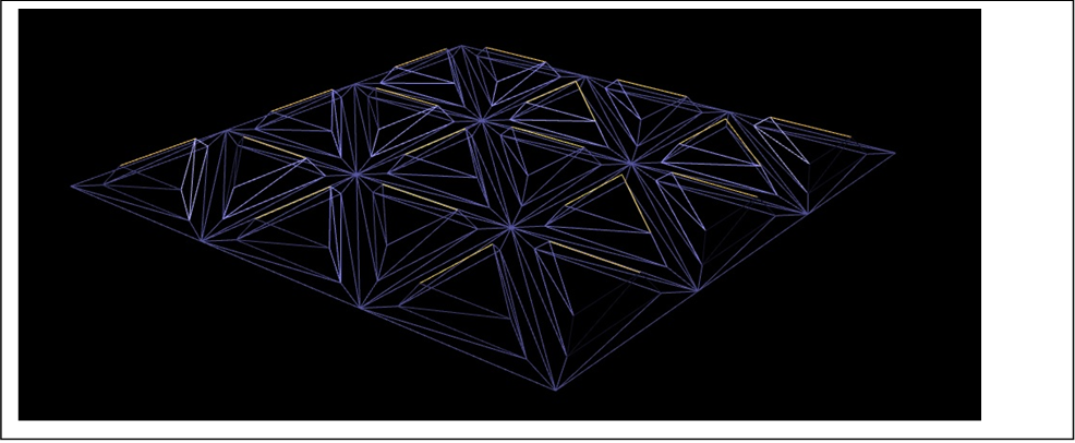
6. The geometry shader replaces each triangle (from the ground plane mesh) with a raised triangle in the center of the original triangle. Each triangle thus becomes a flat region at y=0, surrounding “walls” that rise up to a higher triangle in the center.
7. Each of the three portions (the y=0 region, the walls, and the raised triangle) get a different color. The demo used dark blue, medium blue, and yellow/orange color. But please feel free to improve on these colors. (A nice choice of colors can help compensate in your grade for any other problems.)
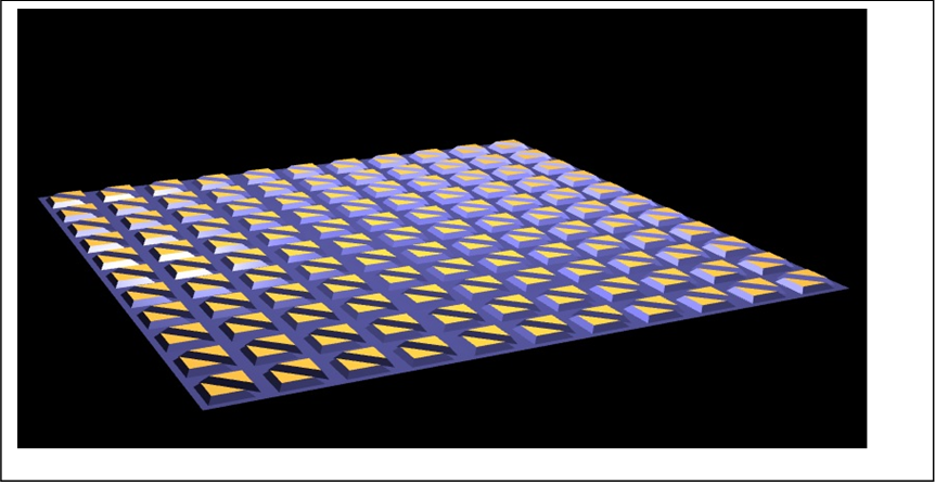
8. When the ground plane is remeshed, the triangles get smaller. The geometry generated by the geometry shader scales proportionally.
9. The first lines of your
geometry shader will be something like:
#version 330 core
layout(triangles) in; // inputs
are triangles
layout(triangle_strip, max_vertices = 23) out; // outputs are triangle
strips
The max_vertices value might need to be bigger than 23. This depends on
your code, and should be an upper bound on the number of time EmitVertex()
is called in the geometry shader. (The documentation states that results are
unpredictable otherwise.)
10. The geometry shader calls EmitVertex() to output vertices, and EndPrimitive() to finalize each triangle strip. A single triangle is generated by a triangle strip with only three vertices.
11. The geometry will need
to have the out variables:
out vec3 mvPos; // Vertex position in modelview coordinates
out vec3 mvNormalFront; // Normal vector to vertex in modelview
coordinates
out vec3 matEmissive;
out vec3 matAmbient;
out vec3 matDiffuse;
out vec3 matSpecular;
out float matSpecExponent;
out float useFresnel;
out vec2 theTexCoords;
because these values are needed as inputs to the fragment shader (which will
not be changed). These values must be written to every time before EmitVertex
is called, except theTexCoords does not need to be written to, since the
fragment shader will ignore its value since we are not using textures. Many of
these values will come directly from the vertex shader. You will need to
modify the vertex shader to gives its “out” variables different names, so that
the geometry shader can take them as inputs. (For instance, I renamed
“matEmissive” to “matEmissive_Base” in my code.) This are input to the
geometry shader as arrays of values, one value per vertex of the current
triangle. Except for mvPos, the values will be the same for all three
vertices.
12. The geometry shader will be easiest to write if it uses the original vertex position: this will make it easier to compute the new geometry. It will need to output however, the position and normal in modelview (world) coordinates for use by the fragment shader. The fragment shader works in world coordinates to compute the Phong lighting. The geometry shader will also need to set gl_Position with the aid of the projection matrix, so that the vertices are placed correctly on the screen!
13. Using barycentric coordinates can simplify calculation (x- and z-) coordinates of vertices needed for the geometry shader.
14. Since this is your first time to write a geometry shader, please expect some problems to occur. Please ask for help as needed. You may want to first write a simplified version of the geometry shader just to test that you understand how geometry shaders work. (For instance, just pass through the triangle unchanged, except for diffuse color.)
15. When you are debugging, please always check the console output window to make sure there no compilation or linkage errors!
16. If you look very closely, you will see the light spheres are affected by the shader program with little triangular bumps. You could fix this by swapping in a second shader, but it is not required for this project.
Hand in procedure: FIRST: Upload all your code to the google drive folder that was shared to you already for Projects 1 and 2. SECOND: Hand in a PDF to gradescope. Include an image, and the acknowledgement of assistance statement.
Grading: Grading is an individual zoom session with Jon Pham or Professor Buss.
SEE FOUR IMAGES BELOW.